Quick-Start Guide | FULL Instructions
INSTALLATION Guide
INSTALLATION Guide
INSTALLATION Guide
1. Site Preparation
1. Site Preparation
1. Site Preparation
Probe each location for boulders or buried debris
Probe each location for boulders or buried debris
Mark every footing center
Mark every footing center
Set string lines and finished grade
Set string lines and finished grade
Relocate any spot that won’t install cleanly
Relocate any spot that won’t install cleanly
Arrive with layout done — rental time is for driving screws
Arrive with layout done — rental time is for driving screws
2. Site Layout
2. Site Layout
2. Site Layout
Confirm screw positions against the project layout
Confirm screw positions against the project layout
Use string line for straight rows and even spacing
Use string line for straight rows and even spacing
Keep clear working room for driver, torque arm, and operator
Keep clear working room for driver, torque arm, and operator
3. Electric Driver Operation
3. Electric Driver Operation
3. Electric Driver Operation
Brace the torque arm before touching the trigger
Brace the torque arm before touching the trigger
Check driver, adapter, and bit connections
Check driver, adapter, and bit connections
Wait 5 seconds after any trigger pull before restarting
Wait 5 seconds after any trigger pull before restarting
If High / Low won’t shift, feather the trigger until it aligns
If High / Low won’t shift, feather the trigger until it aligns
4. Torque Arm & Driving
4. Torque Arm & Driving
4. Torque Arm & Driving
Pick a brace point with room for full arm retraction
Pick a brace point with room for full arm retraction
Start in High Gear; shift to Low when the motor strains
Start in High Gear; shift to Low when the motor strains
Keep the screw plumb for the first 18–24 inches
Keep the screw plumb for the first 18–24 inches
Use Low Gear for final depth and grade only
Use Low Gear for final depth and grade only
Stop and relocate if the arm bottoms out or soil churns
Stop and relocate if the arm bottoms out or soil churns
5. Grade | Elevation
5. Grade | Elevation
5. Grade | Elevation
Verify grade with the survey rod on the torque-arm plate
Verify grade with the survey rod on the torque-arm plate
Finish all screws at one laser or level reference
Finish all screws at one laser or level reference
Make height corrections in Low Gear only
Make height corrections in Low Gear only
Follow the Five-Second Rule before re-triggering
Follow the Five-Second Rule before re-triggering
6. Saddles | Connections
6. Saddles | Connections
6. Saddles | Connections
Leave saddle bolts loose at first
Leave saddle bolts loose at first
Level posts and beams, then tighten the three set bolts
Level posts and beams, then tighten the three set bolts
Add timber locks and through-bolts after alignment
Add timber locks and through-bolts after alignment
7. Field Notes
7. Field Notes
7. Field Notes
Finish probing, layout, and string lines before pickup
Finish probing, layout, and string lines before pickup
Set elevation references ahead of time
Set elevation references ahead of time
If you hit rock or debris, move to an alternate spot — don’t force it
If you hit rock or debris, move to an alternate spot — don’t force it
8. Stop | Check
8. Stop | Check
8. Stop | Check
Stop if the arm runs out of retraction room
Stop if the arm runs out of retraction room
Stop if the screw loses plumb or the motor stalls repeatedly
Stop if the screw loses plumb or the motor stalls repeatedly
Stop if material churns continuously at the surface
Stop if material churns continuously at the surface
Re-check brace point, position, and soil before continuing
Re-check brace point, position, and soil before continuing
FULL INSTRUCTIONS
FULL INSTRUCTIONS
FULL INSTRUCTIONS
01
IDENTIFY POWER SOURCE
IDENTIFY POWER SOURCE
IDENTIFY POWER SOURCE
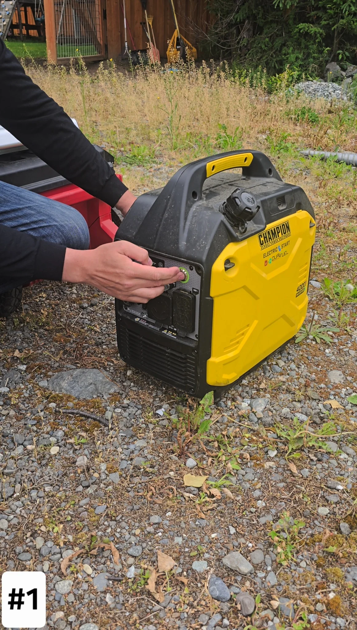
The electric driver runs on a 20 amp breaker or the 4,000 watt rental generator provided by Alaska Ground Screw. Confirm your power before you load out.
The electric driver runs on a 20 amp breaker or the 4,000 watt rental generator provided by Alaska Ground Screw. Confirm your power before you load out.
02
ALASKA GROUND SCREW PACKOUT
ALASKA GROUND SCREW PACKOUT
ALASKA GROUND SCREW PACKOUT
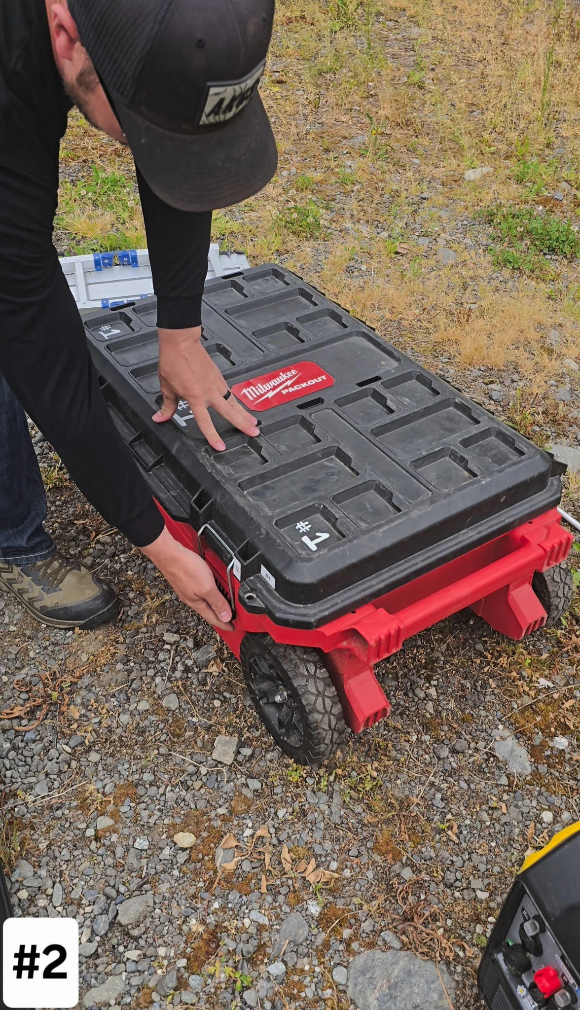
Everything rolls in one box. Keep it near the hole so tools are in reach and you are not walking back and forth.
Everything rolls in one box. Keep it near the hole so tools are in reach and you are not walking back and forth.
03
LIFT OUT THE TOP TRAY
LIFT OUT THE TOP TRAY
LIFT OUT THE TOP TRAY
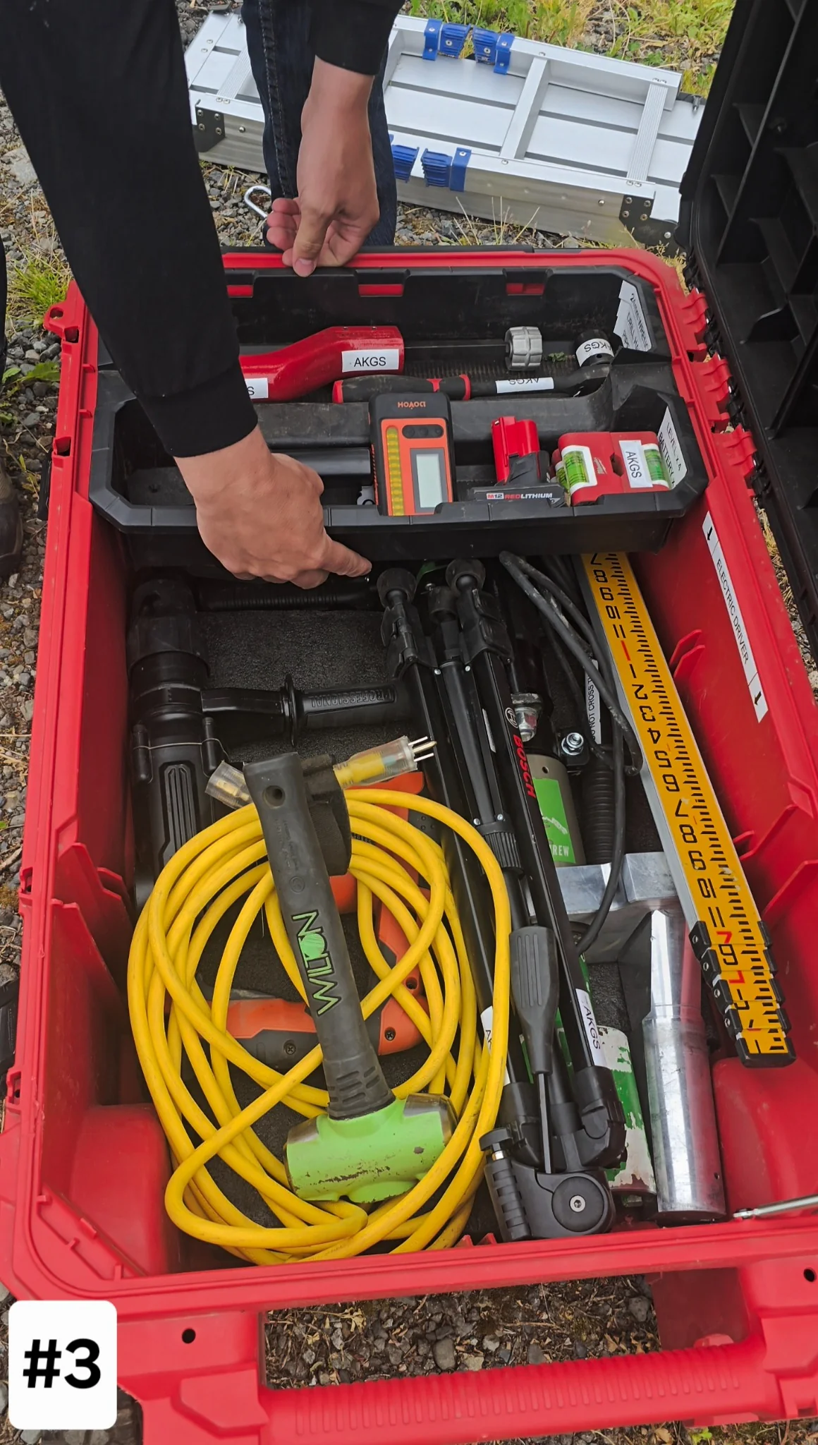
Pull the tool tray and the loose items out of the way to reach the electric driver and the SDS Max drill underneath.
Pull the tool tray and the loose items out of the way to reach the electric driver and the SDS Max drill underneath.
04
PLUg-IN 25ft Extension CORD (20 amp)
PLUg-IN 25ft Extension CORD (20 amp)
PLUg-IN 25ft Extension CORD (20 amp)
Run the provided 25-foot cord into the generator or a 20 amp house outlet. Going longer than 25 feet, check voltage drop first or the driver will run weak.
Run the provided 25-foot cord into the generator or a 20 amp house outlet. Going longer than 25 feet, check voltage drop first or the driver will run weak.

05
BRING THE PLANO TUBE TO THE SITE
BRING THE PLANO TUBE TO THE SITE
BRING THE PLANO TUBE TO THE SITE
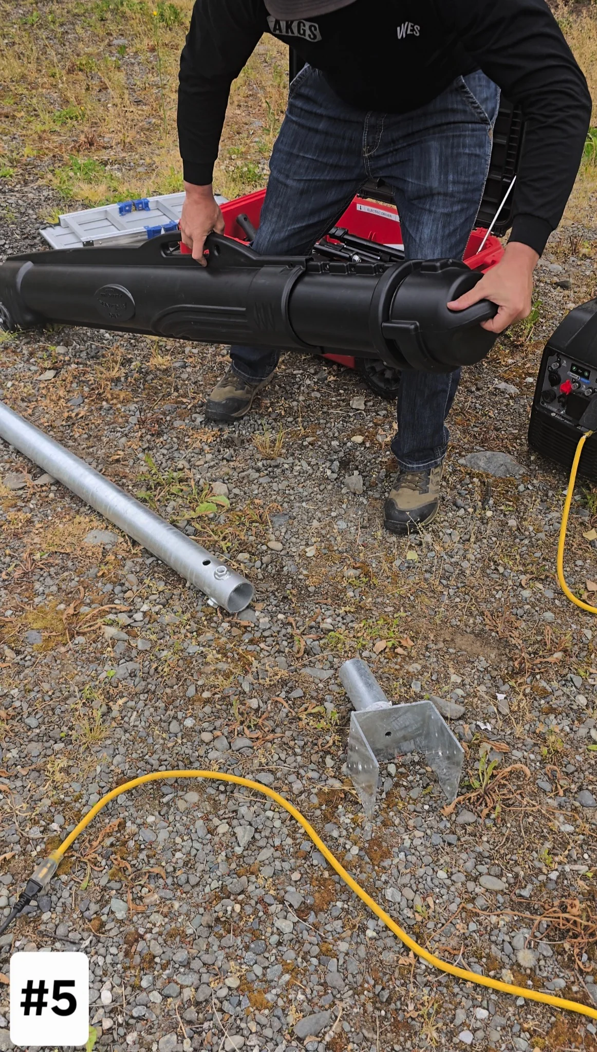
The long tube carries the SDS bit, torque arm, and tent spike. Move it to your install spot so the long steel is right where you need it.
The long tube carries the SDS bit, torque arm, and tent spike. Move it to your install spot so the long steel is right where you need it.
06
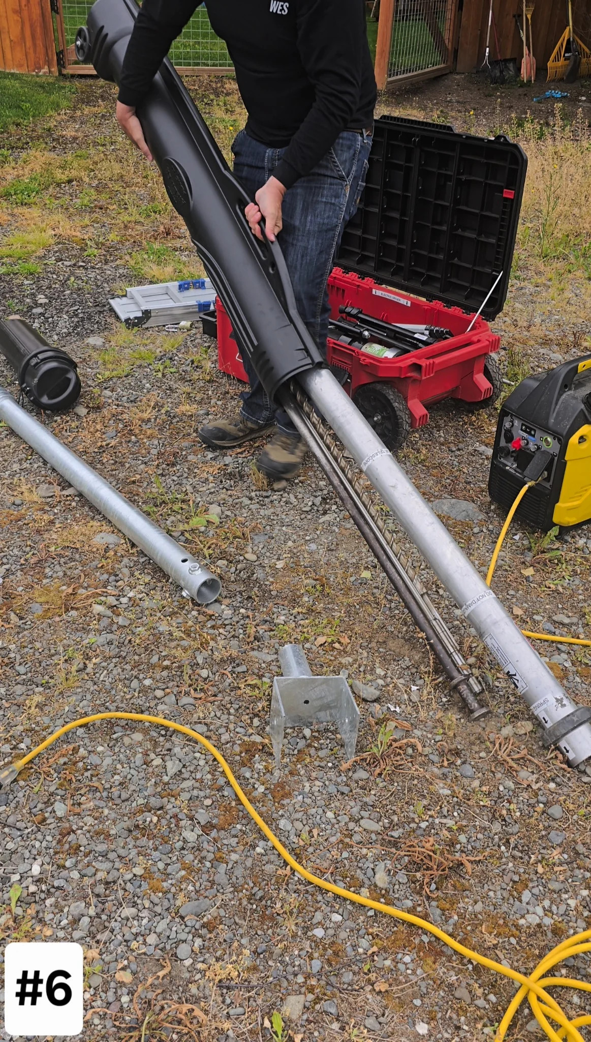
DUMP THE TUBE OUT AT THE SITE
DUMP THE TUBE OUT AT THE SITE
DUMP THE TUBE OUT AT THE SITE
Slide the contents out near your project so the SDS bit, torque arm, and spike are staged and in reach.
Slide the contents out near your project so the SDS bit, torque arm, and spike are staged and in reach.
07
Grab sds max bit
Grab sds max bit
Grab sds max bit
Locate the 36 inch SDS Max bit in the pile.
Locate the 36 inch SDS Max bit in the pile.

08
Install SDS MAX BIT
Install SDS MAX BIT
Install SDS MAX BIT
Install the 36 inch SDS Max bit into the SDS drill. Pull back the collar, seat the bit fully, then tug it to confirm it locked.
Install the 36 inch SDS Max bit into the SDS drill. Pull back the collar, seat the bit fully, then tug it to confirm it locked.

09
USE torpedo levels for pilot hole
USE torpedo levels for pilot hole
USE torpedo levels for pilot hole
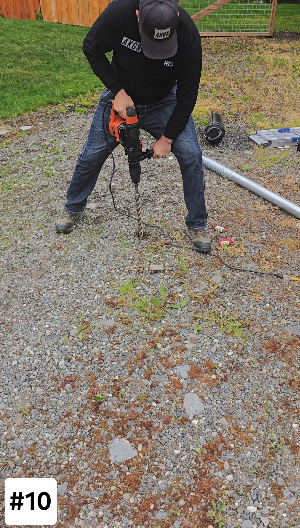
Set torpedo levels on two sides of the bit to check plumb. Correct your angle before you drill.
Set torpedo levels on two sides of the bit to check plumb. Correct your angle before you drill.

10
Ensure A level pilot hole
Ensure A level pilot hole
Ensure A level pilot hole
Drill in stages and re-check plumb three times before you reach full depth. Small corrections early beat a crooked screw later.
Drill in stages and re-check plumb three times before you reach full depth. Small corrections early beat a crooked screw later.
11
INstall 3 | m16 bolts
INstall 3 | m16 bolts
INstall 3 | m16 bolts
Install the three M16 bolts finger tight.
Install the three M16 bolts finger tight.

12
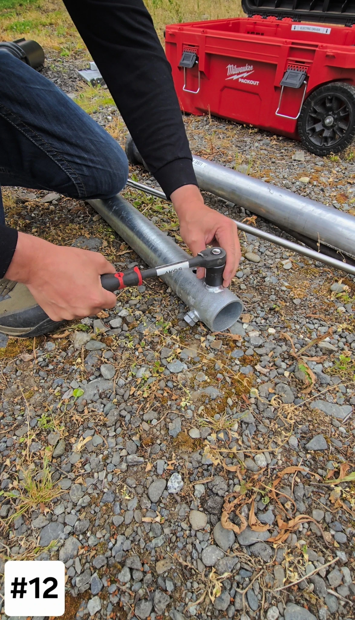
tighten 3 | M16 Bolts (optional)
tighten 3 | M16 Bolts (optional)
tighten 3 | M16 Bolts (optional)
Run the three M16 bolts snug before driving. It protects the welded nuts from ovaling under torque.
Run the three M16 bolts snug before driving. It protects the welded nuts from ovaling under torque.
13
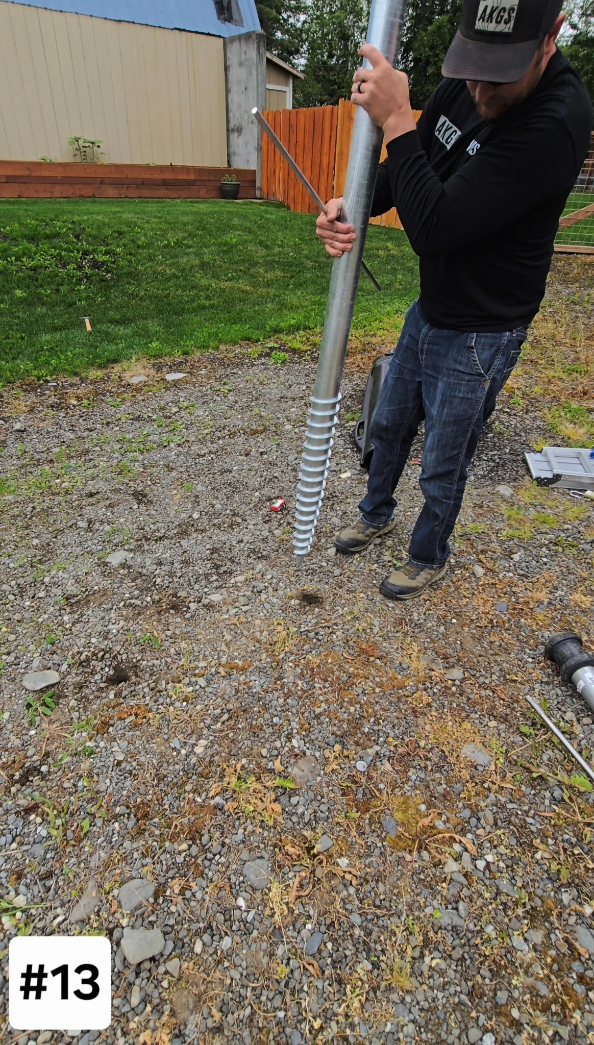
Start Screw by Hand
Start Screw by Hand
Start Screw by Hand
Start the screw into the pilot hole by hand.
Start the screw into the pilot hole by hand.
14
THread Screw for Stability
THread Screw for Stability
THread Screw for Stability
Start the threads until the screw holds itself upright. Working alone, that is what lets you place the driver without a second set of hands.
Start the threads until the screw holds itself upright. Working alone, that is what lets you place the driver without a second set of hands.

15
Add 2-4 Torpedo levels
Add 2-4 Torpedo levels
Add 2-4 Torpedo levels
Add a short instruction here.
Add a short instruction here.

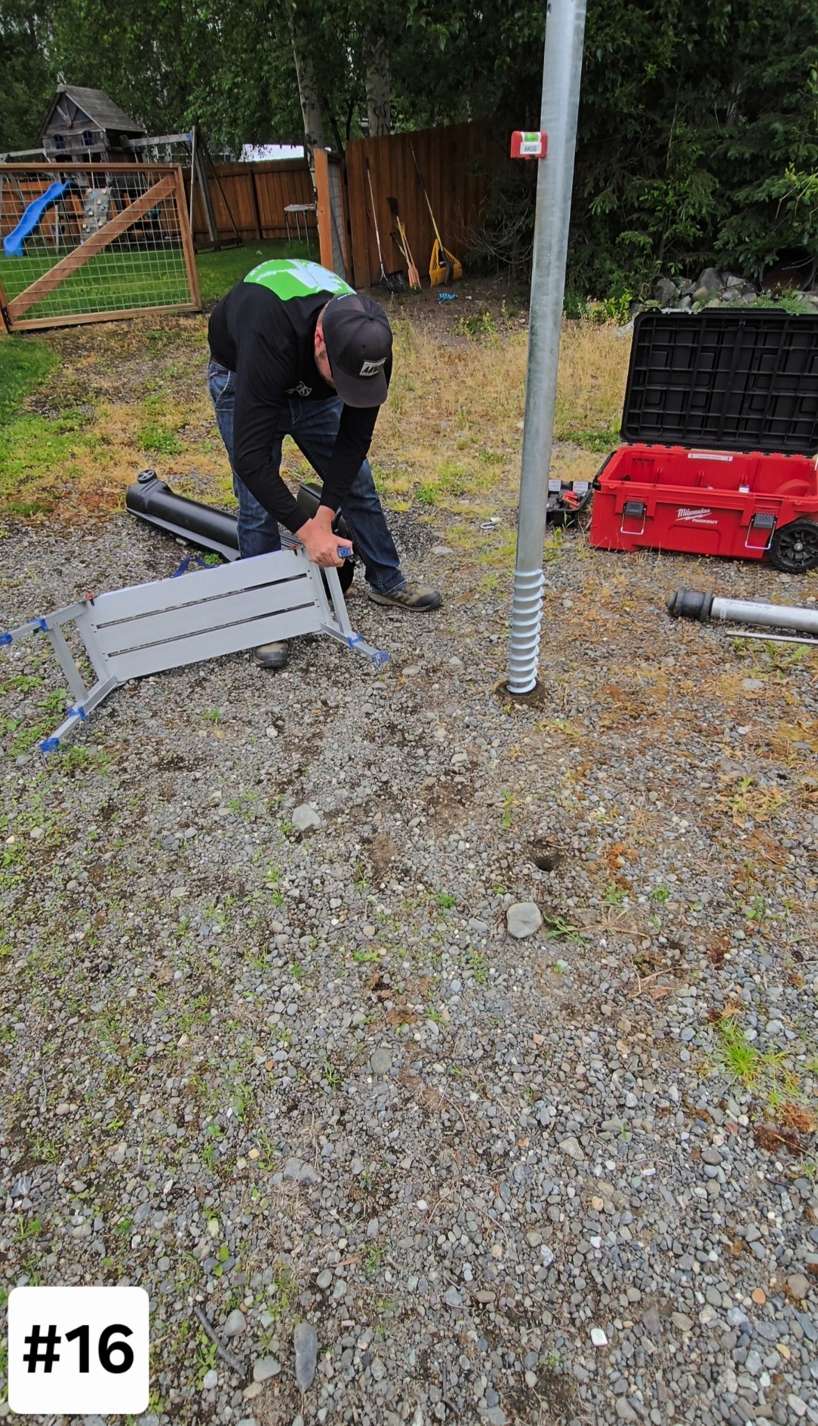
16
Adjust work patform legs
Adjust work patform legs
Adjust work patform legs
Add a short instruction here.
Add a short instruction here.
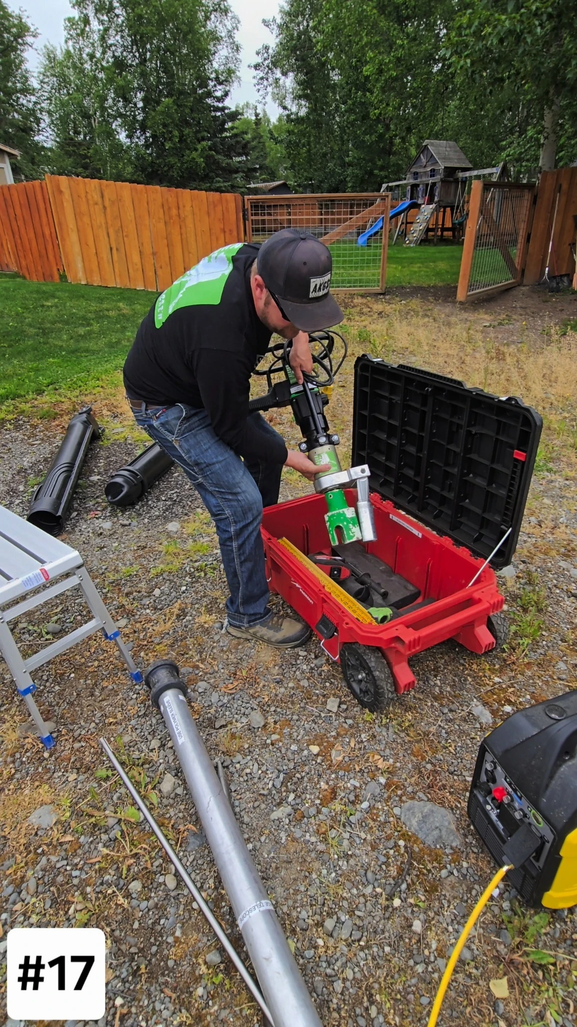
17
Grab Electric Driver
Grab Electric Driver
Grab Electric Driver
Add a short instruction here.
Add a short instruction here.
18
Install Electric driver handle
Install Electric driver handle
Install Electric driver handle
Add a short instruction here.
Add a short instruction here.

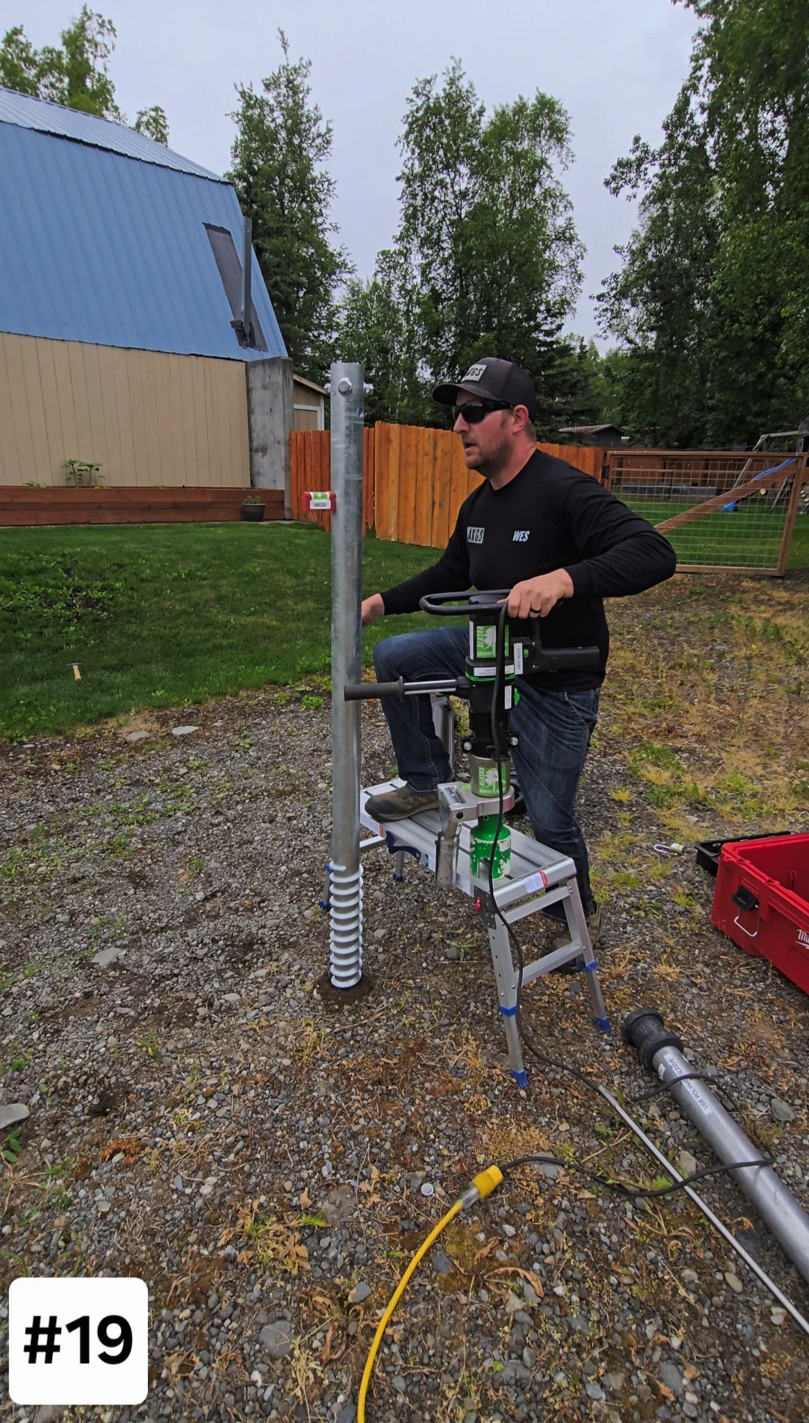
19
Place Electric Driver on Platform
Place Electric Driver on Platform
Place Electric Driver on Platform
Add a short instruction here.
Add a short instruction here.
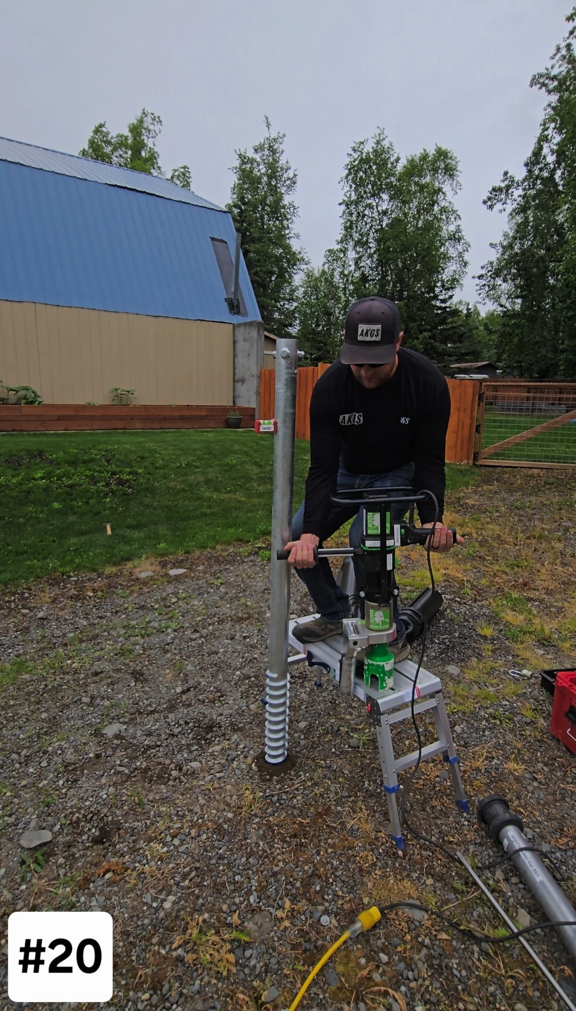
20
Lift Electric Driver From Platform to screw
Lift Electric Driver From Platform to screw
Lift Electric Driver From Platform to screw
Add a short instruction here.
Add a short instruction here.
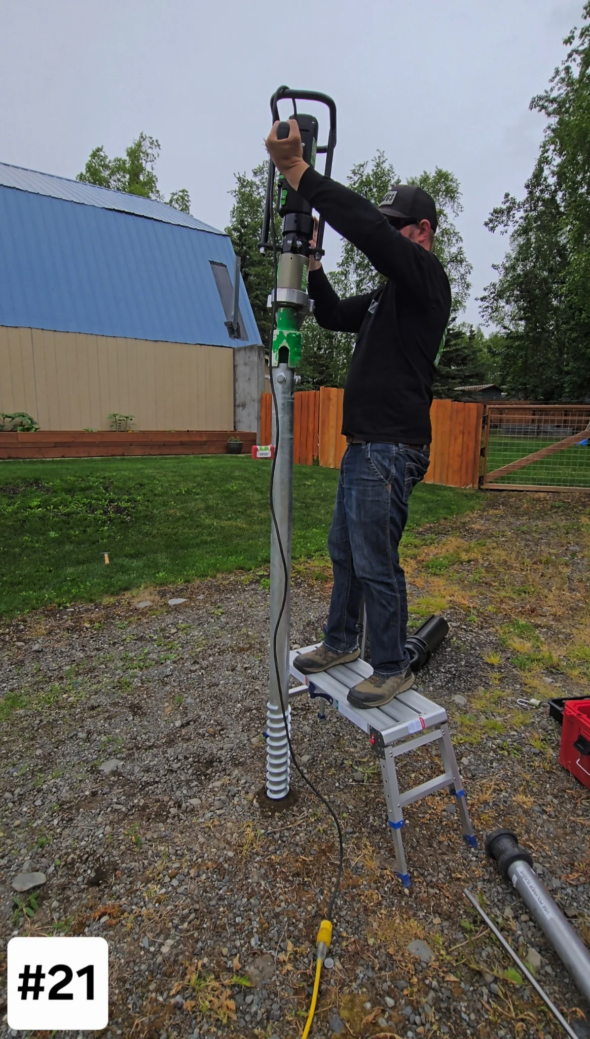
21
Place electric driver on top of screw
Place electric driver on top of screw
Place electric driver on top of screw
Add a short instruction here.
Add a short instruction here.
22
torque arm | Telescope out
torque arm | Telescope out
torque arm | Telescope out
Add a short instruction here.
Add a short instruction here.

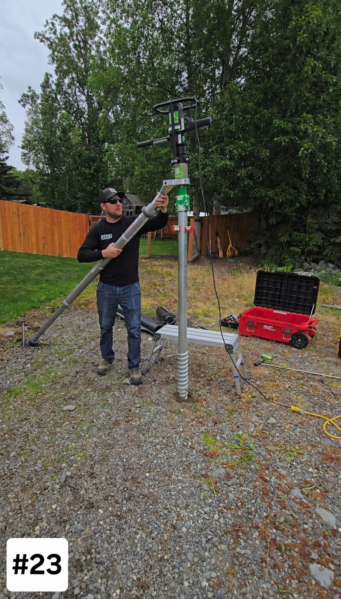
23
Attach Torque arm to Electric Driver
Attach Torque arm to Electric Driver
Attach Torque arm to Electric Driver
Add a short instruction here.
Add a short instruction here.
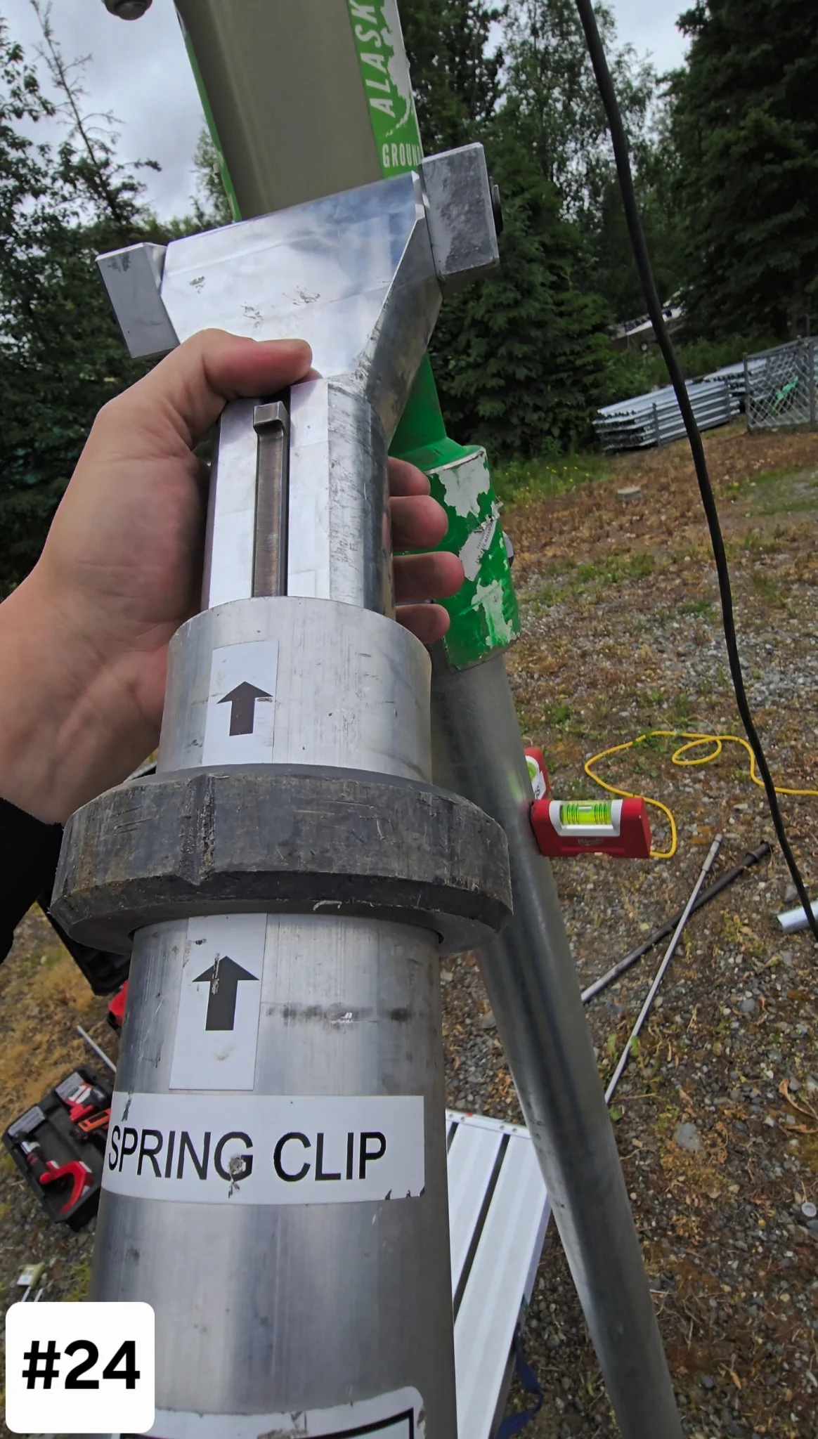
24
Line-up Torque arm Securment Spring Clip
Line-up Torque arm Securment Spring Clip
Line-up Torque arm Securment Spring Clip
Add a short instruction here.
Add a short instruction here.
25
Align Tent Spike | Right to DRIVE
Align Tent Spike | Right to DRIVE
Align Tent Spike | Right to DRIVE
Add a short instruction here.
Add a short instruction here.

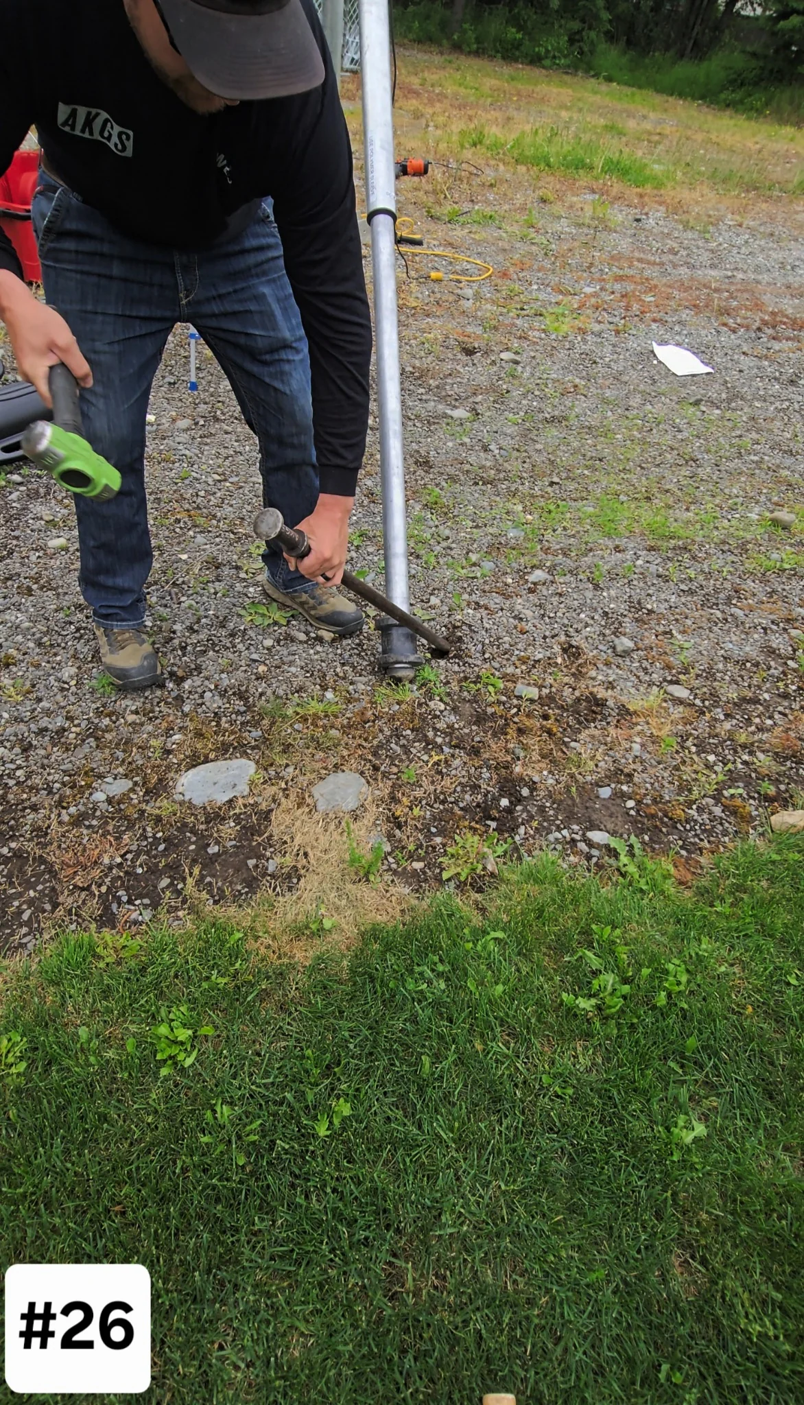
26
Align Tent spike on polymer Sleeve
Align Tent spike on polymer Sleeve
Align Tent spike on polymer Sleeve
Add a short instruction here.
Add a short instruction here.
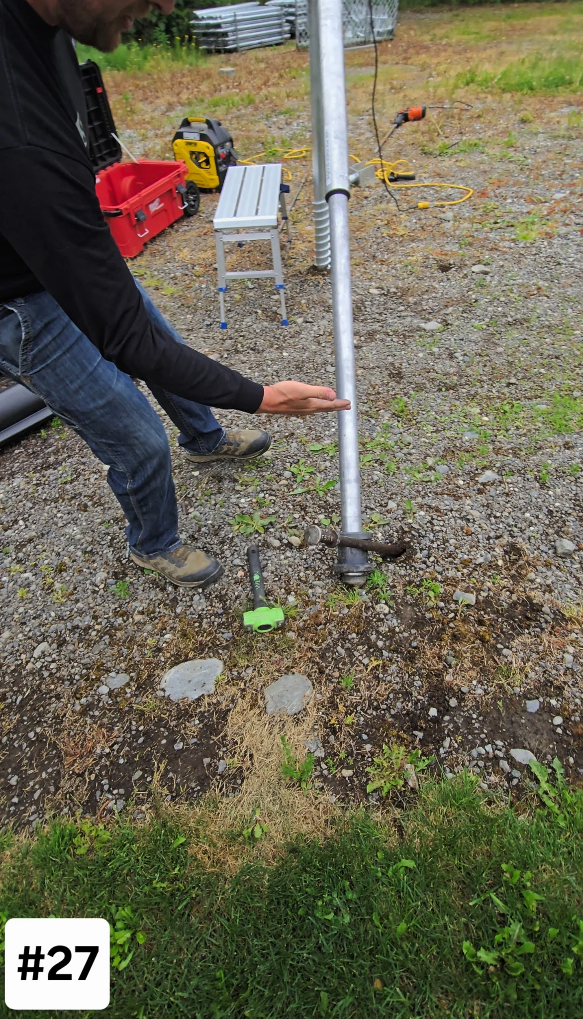
27
Align Tent spike with proper angle
Align Tent spike with proper angle
Align Tent spike with proper angle
Add a short instruction here.
Add a short instruction here.
28
Start install in HIgh gear | 7 rpm
Start install in HIgh gear | 7 rpm
Start install in HIgh gear | 7 rpm
Add a short instruction here.
Add a short instruction here.

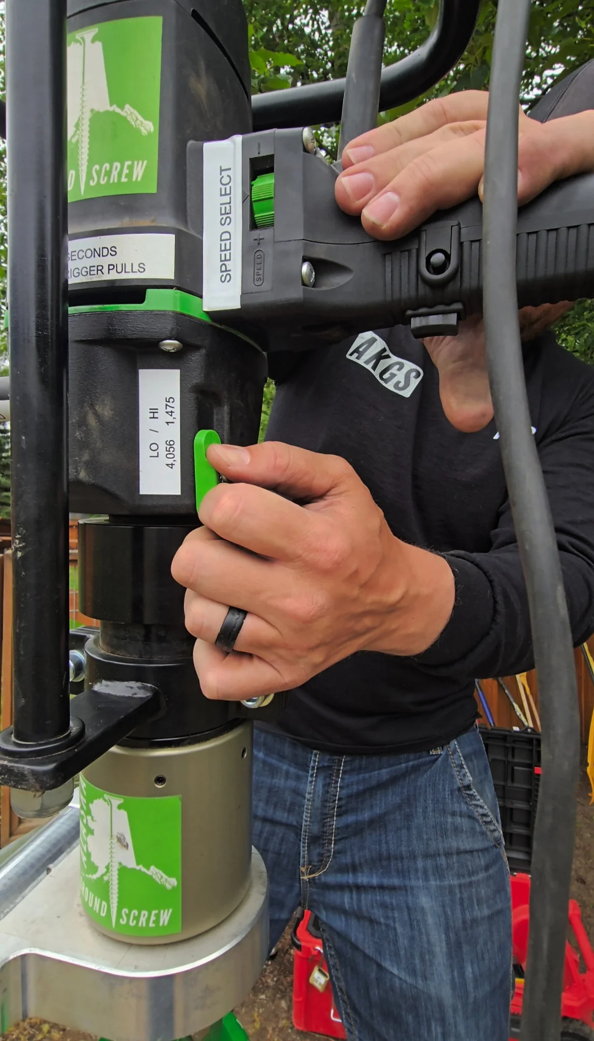
29
Trigger & gear slector Simultaneously
Trigger & gear slector Simultaneously
Trigger & gear slector Simultaneously
Add a short instruction here.
Add a short instruction here.
30
Continue INSTALL in low gear | 2 rpm
Continue INSTALL in low gear | 2 rpm
Continue INSTALL in low gear | 2 rpm
Add a short instruction here.
Add a short instruction here.

CAUTION ELECTRIC DRIVER TORQUE ARM
CAUTION ELECTRIC DRIVER TORQUE ARM
CAUTION ELECTRIC DRIVER TORQUE ARM
Chart Represents: Torque Arm Force at each arm length.
Color Codes: User safety only and does not affect performance.
Chart Represents: Torque Arm Force at each arm length.
Color Codes: User safety only and does not affect performance.
RADIUS
RADIUS
1’
1’
2’
2’
3’
3’
4’
4’
5’
5’
6’
6’
7’
7’
8’
8’
9’
9’
10’
10’
FT/LBS
FT/LBS
HIGH GEAR
HIGH
GEAR
1,475
1475
737
737
491
491
368
368
295
295
245
245
210
210
184
184
163
163
147
147
LOW GEAR
LOW
GEAR
4,056
4056
2,028
2028
1,352
1352
1,014
1014
811
811
676
676
579
579
507
507
450
450
405
405
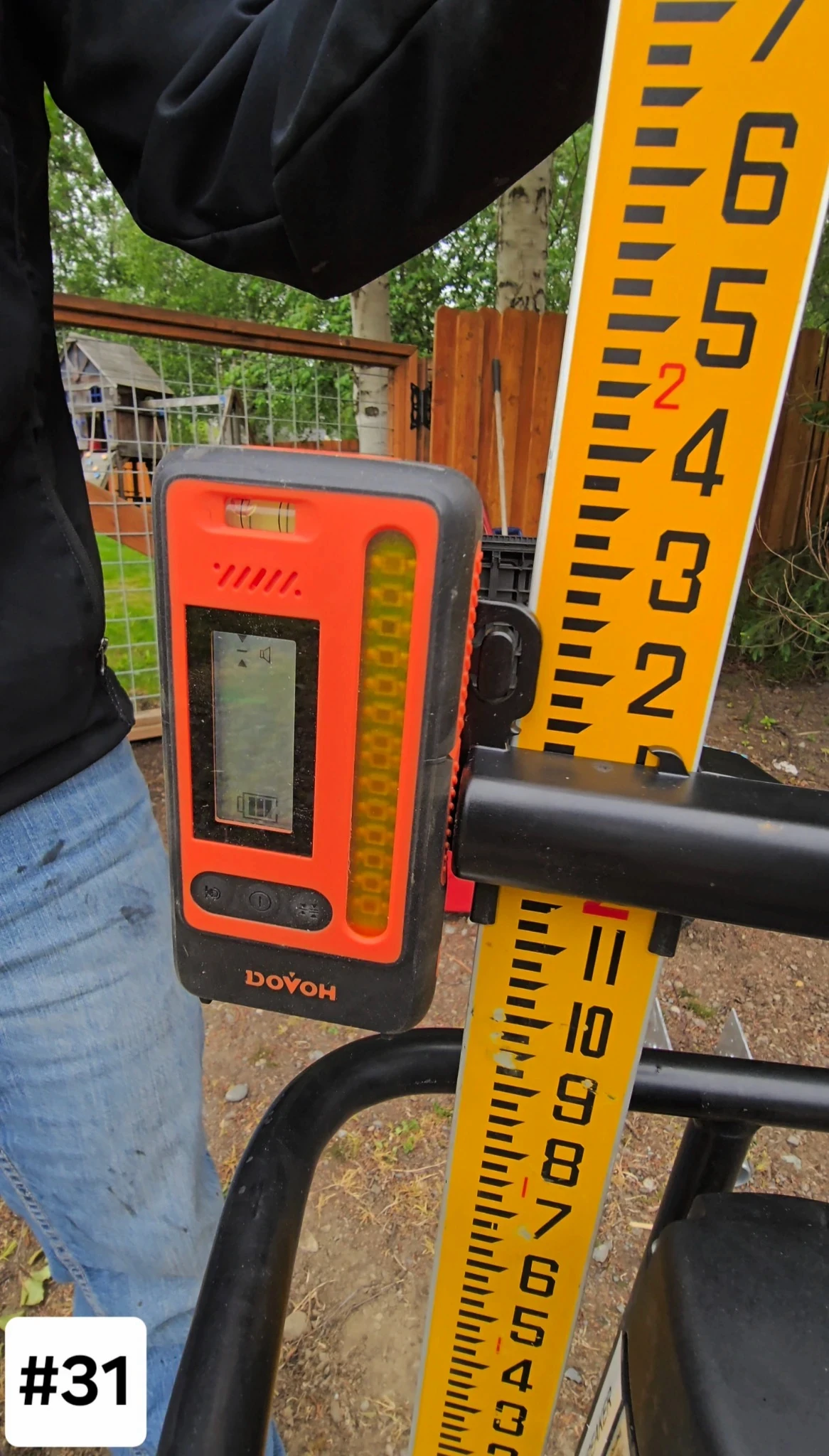
31
laser level & Survey rod for final grade
laser level & Survey rod for final grade
laser level & Survey rod for final grade
Add a short instruction here.
Add a short instruction here.
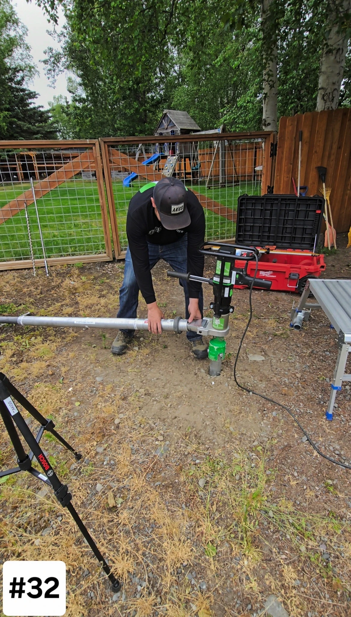
32
Remove torque arm
Remove torque arm
Remove torque arm
Add a short instruction here.
Add a short instruction here.
33
Remove electric driver
Remove electric driver
Remove electric driver
Add a short instruction here.
Add a short instruction here.

34
place electric driver away from dirt or water
place electric driver away from dirt or water
place electric driver away from dirt or water
Add a short instruction here.
Add a short instruction here.

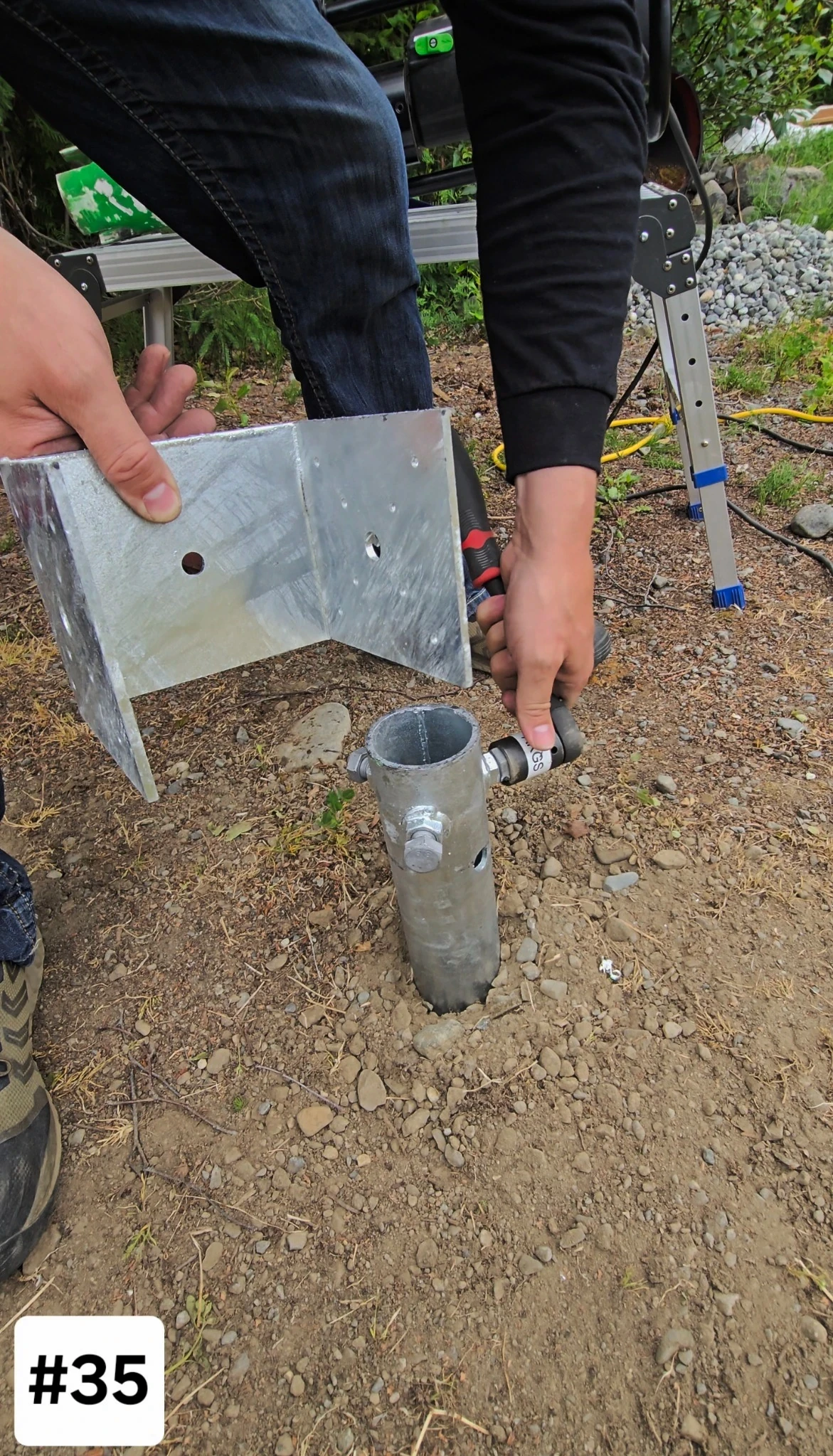
35
Loosen 3 | M16 bolts
Loosen 3 | M16 bolts
Loosen 3 | M16 bolts
Add a short instruction here.
Add a short instruction here.
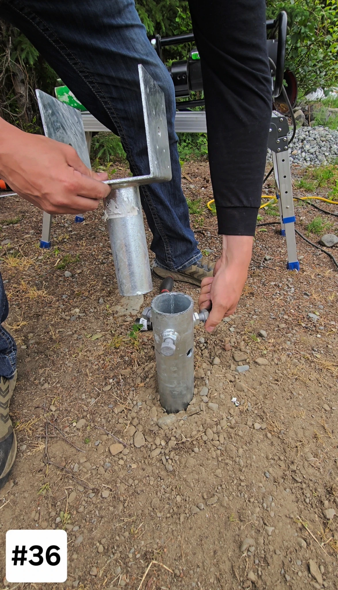
36
Place saddle into ground screw
Place saddle into ground screw
Place saddle into ground screw
Add a short instruction here.
Add a short instruction here.
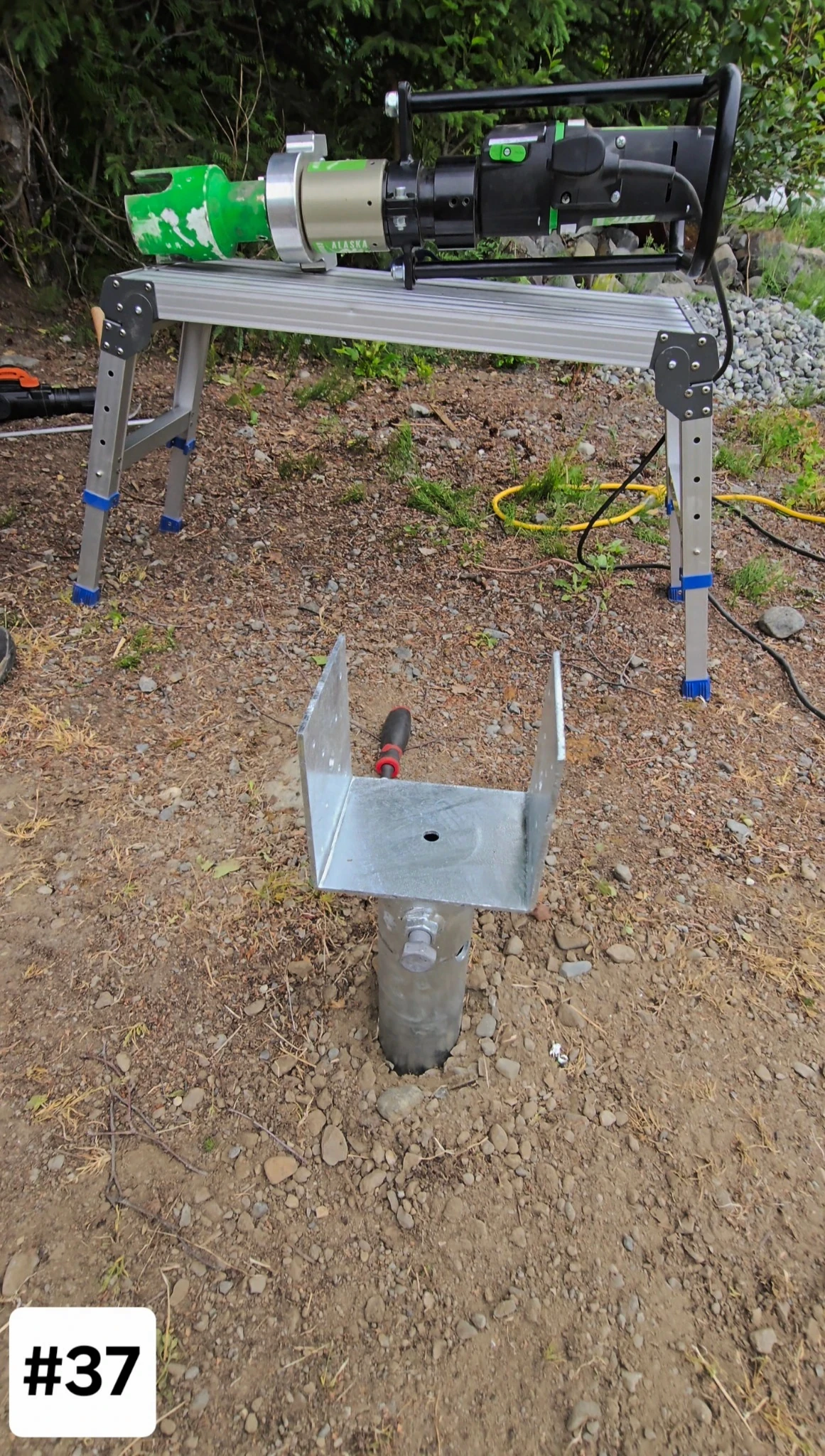
37
Set final saddle direction
Set final saddle direction
Set final saddle direction
Add a short instruction here.
Add a short instruction here.
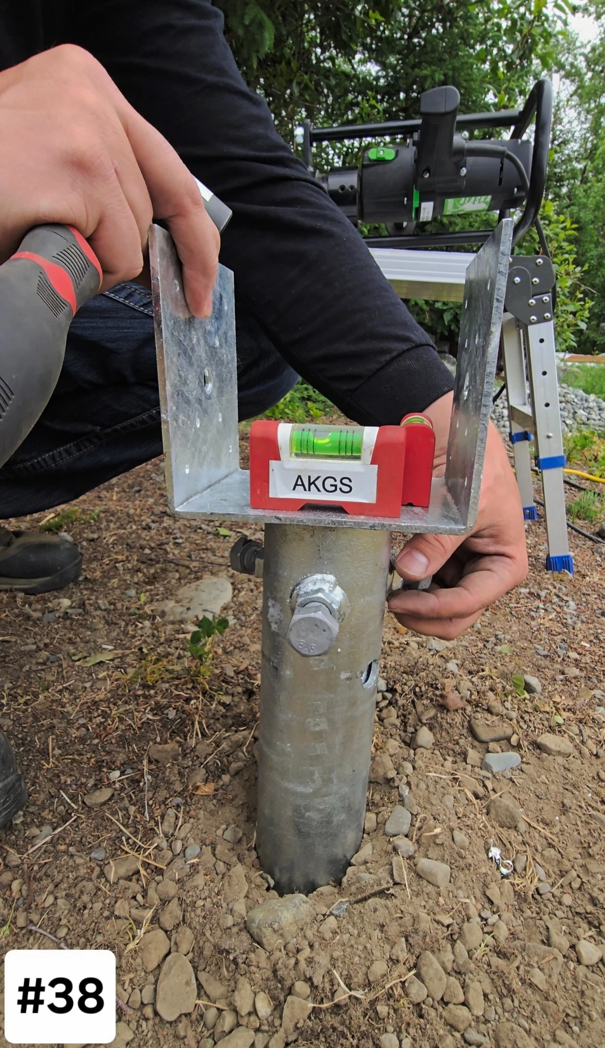
38
Level saddle with 3 | M16 Bolts
Level saddle with 3 | M16 Bolts
Level saddle with 3 | M16 Bolts
Add a short instruction here.
Add a short instruction here.
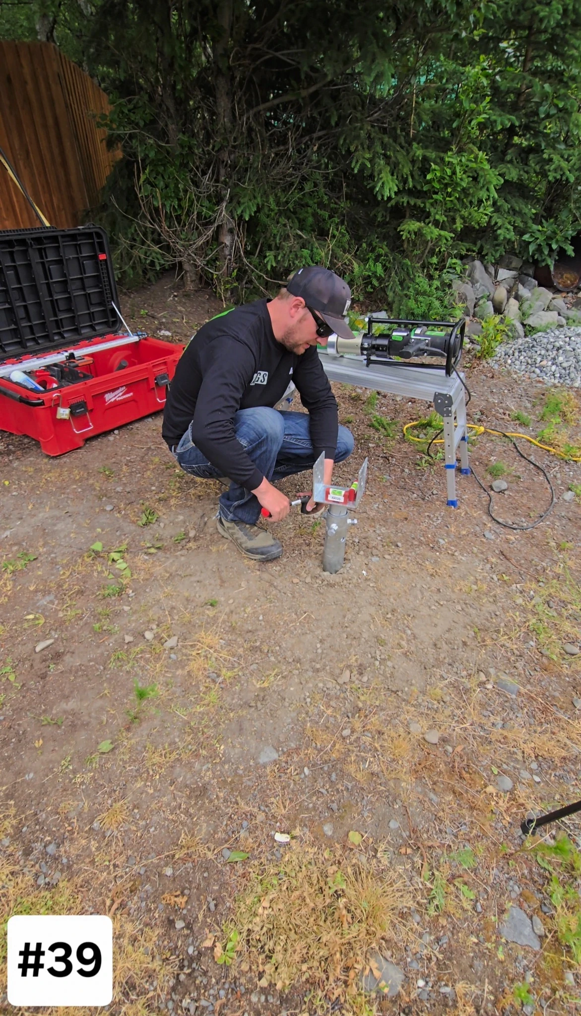
39
Tighten Saddle bolts to level
Tighten Saddle bolts to level
Tighten Saddle bolts to level
Add a short instruction here.
Add a short instruction here.
40
Enjoy Your Build
Enjoy Your Build
Enjoy Your Build
Keep us in mind for your next project.
Keep us in mind for your next project.
